WELCOME TO

Advanced IC Engineering, Inc

Hardware and Software Engineering Services 

 Updated August 2019


ADVICE Engineering Services

Advanced IC Engineering, Inc. has been designing Data Communication, Process Control Systems, Test and Monitoring products and providing both hardware and software engineering design and consulting services since our incorporation in 1989.  We enjoy solving problems and take pride in creating devices that work well. 
Completing a project involves getting many details right the first time - we know how to do it without straining our client's resources.

Full Design Engineering - Need a new product developed fast? We provide full top-down design of complex systems or individual components of a system.

Reverse Engineering - Lost your design? Don’t be embarrassed, it happens! We can take a PC board and deliver schematics, new Gerber files, prototypes and assemblies.

Re-Engineering - Want to add new features, but have lost your in-house engineering capabilities or the design authority has moved on? We can take existing designs, update them and complete them.

Compliance Design Analysis - Getting ready to go for UL, CSA, FM, VDE, FCC certifications? We have the experience to take your product through the certification process and recommend corrections to help your unit pass.

Design Review - Need an independent outside opinion of a new product? We can provide engineering and manufacturing analysis of your new product during any phase of its design.

RoHS compliance - Need to make your product lead-free? We can find the right components to make that happen.

Supporting Services

  • PC Board Design, Schematic Entry, and Layout
  • Prototype Development
  • Front panel design and development
  • Electronics Manufacturing
  • Software Application Development (Unix or Windows, Basic, C, C++, Java, Phthon)
  • Device Driver Software (Assembly, C)
  • Systems Engineering
  • Project Management
  • Systems Integration
  • Electronics Repair
  • Technical Documentation (Schematics to Brochures)
  • Patent Development

Capabilities

PC Board Design, Layout, Manufacturing and Testing

ADVICE designs and manufactures circuit boards and systems for companies in a variety of fields. We have the experience to navigate products through patent and certification processes. We can coordinate rapid turnaround on prototypes and can react quickly to changing requirements.
  • CAD and Mechanical
    • AutoCAD, AutoSketch
    • Solid Works
  • Schematic Capture
    • Accell Tango Schematic II
    • OrCAD 3/4/7/9
    • ViewLogic
  • PCB Layout
    • Accell Tango PCB plus and Route plus
    • Supports up to 12 layers, thru-hole and surface mount down to 0.1mm pitch
    • Other layout systems available
  • PAL and FPGA
    • AMD Mach, Xilinx, Atmel, Lattice
  • Our Lab is fully equipped with Oscilloscopes, Logic Analyzer, VOMs, Milling Machine, CNC Router, Bench Power Supplies, Function Generators, PIC Development Systems, Voice Chip Development Systems, FPGA/PROM/Flash/Microcontroller programmers, 68000 Emulator, Digital Thermometers, and complete SMT rework stations, plus much more. 

RECENT WORK


Instrumentation

Communication

Analog to Digital

Digital Control

PRODUCTS & SERVICES

Advice provides hardware and software solutions in many packages.  We have a very strong background in communications, digital and analog design.  We cover both embedded and system software.    

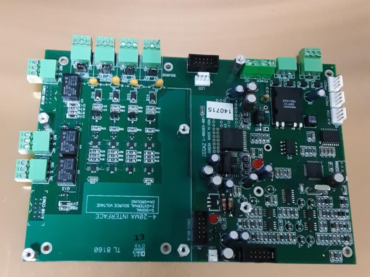
Example of one of our system designs


This product was designed for Zegaz Insturments to work with their Hydrocarbon Dewpoint Analysis  System (HCD-5000).  It couples to a microcomputer provides RS232, RS485, 4-20mA, User Relays as well as operate the patented dewpoint cell.  

Advice Photo Gallery

CONTACT US

Call or email us with any questions you may have.

We receive a lot of email and it is easy to get filtered out, so place in the subject line "Inquiry or RFQ"   

Advanced IC Engineering, Inc - Home

410-259-9941

Advanced IC Engineering, Inc - Home

info@advice1.com

Advanced IC Engineering, Inc - Home

Projects@advice1.com

If you have a potential project send the files to this address and give us a call at

410-259-9941.

REFERENCE DOCUMENTATION

V.35 (Really old stuff) 

V.35 has been around for quite some time. It was originally designed for a 48 kbps synchronous modem - that's right, officially its top rated speed is 48 kbps. However, V.35 has been used for many years in applications running from 20 kbps up to and past 2 Mbps. In 1989, CCITT BLUE BOOK (ITU) recommended the interface become obsolete and replaced it with the V.10/V.11 standard. However, V.35 still remains popular, and has evolved to using the specifications from V.11 for the differential signals, while the control signals remain unbalanced. The V.11/V.35 BLUE is fully interoperable with the old V.35 RED interface, except V.35 RED may not handle the speed and distance of the newer spec. In many years of testing, I have not found any system, DSU/CSU, Router, Frame Relay bridge, etc. with incompatible V.35 interfaces.


Most of the V.35 signals are for control and handshake purposes (like RTS, CTS, DSR, DTR) and these are implemented in unbalanced fashion, similar to RS232 / V.24. This approach is simple, inexpensive, and is usually adequate for these relatively invariant signals.


V.35 gets its superior speed and noise immunity by using differential signaling on the data and clock lines. Unlike RS232 / V.24 which uses signals with reference to ground, V.35 receivers look for the difference in potential between a pair of wires. The wires can be at any potential, the signal is carried by voltage differences between the two wires. Now the secret; by twisting these two wires, it becomes likely that noise picked up on one wire will also be picked up on the other. When both wires pick up the same noise it has the affect of cancelling itself - as the same noise impulse on both wires is invisible to the receiver. Remember the receivers are only looking at the difference in voltage level of each wire to the other, not to ground. Many high speed interfaces use this same technique, examples are: RS530, RS449, 10/100/1000baseT.


The differential signals for V.35 are commonly labeled as either "A" and "B". Wire A always connects to A, and B connects to B. Crossing the wires just inverts the data or clock. I have never seen any piece of equipment damaged from this, but they don't work this way, either.


_____________________________________________________________________________________________


V.35 Interface Design

It is important to remember that the CCITT (ITU) in 1989 recommended that V.35 RED is obsolete and recommended that the V.11 (RS422) interface be used for the differential interface. This makes the V.35 BLUE interface easier to design and better in performance. It also removes the need for a -5 Volt power supply. I have built both the new and old V.35 interfaces and have found them to be fully compatible.


V.35 Differential Driver

The resistors Za and Zb are optional. I recommend 10 Ohms to bring the interface to 50 Ohms and to provide some protection from EMF. Here is a Tip: Note that the A or + signal is on the inverted output pin of the driver, most designers get this switched in their first design. This happens because some data books call the positive pin A and the negative pin B. The V.35 A or + must be the inverted pin. This is also true of the receivers.


V.35 Differential Receiver

The resistor Zt is optional. I recommend 150 Ohms to reduce reflectance. However If you are trying to build a non intrusive receiver I would leave this out. Note this interface when left floating will have an unpredictable output. Some engineers place pull up (to pin A) and pull down (to pin B) resistors of 10K to provide a known state when the cable is unplugged or connected equipment is turned off.


V.35 Unbalanced Driver

The typical driver is the standard RS232 driver 1488, however this requires + and - 12 Volts.  Many of the new interfaces are using the V.24 / RS232 driver chips with the charge pump built in, so they only need +5V to operate.  These come in many configuration some include both drivers and receivers.  One of the typical is the DS14C232 from TI or Max 232. 


V.35 Unbalanced Receiver

The typical IC used for the reciever is the 1489, it only requires 5 volts to operate, but most new designs are using the charge pump IC which have both the receivers and drivers in the same chip. 


V.35 Interface 
(some signals not shown)

This shows a typical V.35 interface.  A few signals like LT have not been included.   The box is a M.34 connector set up in the DTE configuration.


_________________________________________


Legal Disclaimer

Advanced IC Engineering (ADVICE) makes no warranties with respect to this documentation and disclaims any implied warranties of merchant-ability and fitness for a particular purpose. ADVICE assumes no responsibility for any errors that may appear on this site. The information contained on this site is subject to change without notice and does not represent a commitment on the part of ADVICE.

Reference Documentation

RS232

  RS232 has been around for a long time.  It works by setting the signals to either a mark (> 9V, typically 12V) and space (< -9V, typically -12V).  As you can imagine this 24V swing is pretty noisy and can cause a lot of cross talk at higher speeds.  That is why it typically does not go much faster than 128Kbps.  

This has been modernized into the 9 pin com port on the PC and sometimes used on a RJ11 (phone jack).


Place Chart of various RS232 interfaces here


UnBalanced RS232 (V.24)

The typical unbalanced driver is the standard RS232 1488 IC, however this requires + and - 12 Volts.  Many of the new interfaces are using the V.24 / RS232 driver chips with the charge pump built in, so they only need +5V to operate.  These come in many configuration some include both drivers and recievers.  Two parts that come to mind is the DS14C232 from TI or Max 232. 


UnBalanced RS232 (V.24) Receiver

The typical IC used for the reciever is the 1489, it only requires 5 volts to operate, but most new designs are using the charge pump IC which have both the receivers and drivers in the same chip. 

Legal Disclaimer


Advanced IC Engineering (ADVICE) makes no warranties with respect to this documentation and disclaims any implied warranties of merchantability and fitness for a particular purpose. ADVICE assumes no responsibility for any errors that may appear on this site. The information contained on this site is subject to change without notice and does not represent a commitment on the part of ADVICE.


If you have comments or questions about the information presented, please contact us.


Reference Documentation

RS449

RS449, which is identical to V.11, relies on balanced differential signaling (RS422) to achieve longer range, higher speeds, and obtain some immunity against common-mode noise. The standard uses a 37-pin D-connector and is intended for synchronous wide area networking applications.

Each pair of differential signals are labeled as "A" and "B". The "A" wire always connects to "A" on the other interface, and "B" connects to "B". 


RS449 Connector (DB-37)


RS449 Speed vs. Distance

Terminated                Unterminated

Speed   Distance           Speed   Distance

10 MHz    10 m           1 MHz    10 m

    2 MHz     40 m          100 kHz   100 m

   1 MHz    100 m           56 kHz    110 m

  100 kHz    1 km            10 kHz     1 km

These are the official speeds according to CCITT, however I have run 1 MHz data over 1 mile on a terminated circuit.  


Place pin out chart here.  


Balanced Driver  (RS422)

The resistors Za and Zb are optional. I recommend 10 Ohms to bring the interface to 50 Ohms and to provide some protection from EMI. Note that the "A" signal is on the inverted output pin of the driver, about 50% of designers get this switched in their first design. This happens because some data books call the positive pin A and the negative pin B. The RS530 (RS422) "A" signal must be the inverted pin. This is also true of the receivers.


Balanced Receiver (RS422)

The resistor Zt is optional. I recommend 150 Ohms to reduce reflectance. Leave Zt out if you are trying to build a non intrusive receiver. Note that this interface, when left floating, will have an unpredictable output. Some engineers install pull up (to pin A) and pull down (to pin B) resistors of 10k Ohms to provide a known state when the cable is unplugged or connected equipment is turned off.


Unbalanced Driver

The typical unbalanced driver is the standard RS232 1488 IC, however this requires + and - 12 Volts.  Many of the new interfaces are using the V.24 / RS232 driver chips with the charge pump built in, so they only need +5V to operate.  These come in many configuration some include both drivers and recievers.  Two parts that come to mind is the DS14C232 from TI or Max 232. 


Unbalanced Receiver

The typical IC used for the reciever is the 1489, it only requires 5 volts to operate, but most new designs are using the charge pump IC which have both the receivers and drivers in the same chip. 


Legal Disclaimer

Advanced IC Engineering (ADVICE) makes no warranties with respect to this documentation and disclaims any implied warranties of merchantability and fitness for a particular purpose. ADVICE assumes no responsibility for any errors that may appear on this site. The information contained on this site is subject to change without notice and does not represent a commitment on the part of ADVICE.


If you have comments or questions about the information presented, please contact us.


Reference Documentation

RS530

RS530 is electrically similar to RS449, but uses a DB25 connector. The smaller connector saves space, and because the DB25 is very commonplace, it is much less expensive.

RS530 employs differential signaling on its send, receive and clocking signals, as well as its control and handshaking signals. The differential signals for RS530 are labeled as either "A and B". At both connectors, wire A always connects to A, and B connects to B.

The RS530 transmitter sends a data 0 (or logic ON) by setting the potential on the A signal to 0.3V (or more) higher than the voltage on the B signal. The transmitter sends a data 1 (or logic OFF) by setting the potential on the B signal to 0.3V or more than the voltage on the A signal. The voltage offset (from ground reference) is not to exceed 3V, however most receivers can handle much more, check the receiver data sheet for exact limits. This approach is relatively immune to noise when the cable is constructed so that the A and B signal wires are a twisted pair. Shielding the cable is generally not required.


Data 0 = A > B + 0.3VData 1 = B > A + 0.3V

Example:Data 0A=2V,B=1VData 1A=1V,B=2V


Most receivers can handle both + and - voltages, again check the data sheet on the part used to be sure. If you have the correct receivers it is possible for the older V.35 (+/-5V) signaling to be wired to RS530 or V.11. This is how Cisco and others get many different interfaces on their Smart Serial connectors, and you thought it was magic!


Place RS530 pinout here


RS530 Design


Differential Driver

The resistors Za and Zb are optional. I recommend 10 Ohms to bring the interface to 50 Ohms and to provide some protection from EMI. Note that the "A" signal is on the inverted output pin of the driver, about 50% of designers get this switched in their first design. This happens because some data books call the positive pin A and the negative pin B. The RS530 (RS422) "A" signal must be the inverted pin. This is also true of the receivers.


Differential Receiver

The resistor Zt is optional. I recommend 150 Ohms to reduce reflectance. Leave Zt out if you are trying to build a non intrusive receiver. Note that this interface, when left floating, will have an unpredictable output. Some engineers install pull up (to pin A) and pull down (to pin B) resistors of 10k Ohms to provide a known state when the cable is unplugged or connected equipment is turned off.


Legal Disclaimer

Advanced IC Engineering (ADVICE) makes no warranties with respect to this documentation and disclaims any implied warranties of merchantability and fitness for a particular purpose. ADVICE assumes no responsibility for any errors that may appear on this site. The information contained on this site is subject to change without notice and does not represent a commitment on the part of ADVICE.


If you have comments or questions about the information presented, please contact us.


 Reference Documentation

Proportional Integral Derivative Control

PID, although developed in the 1940s, has had staying power as a technique for developing closed-loop process control systems. The reason for its longevity is that PID is easily implemented in software and performs well for linear control problems. PID works very well when the suitable gain values are employed and the system responds smoothly over the range of interest. A non-linear system can usually be controlled by dividing it into multiple ranges, and selecting optimal gain values for each range.

PID Equations

E = Setpoint - PV

CV = Kp * E + Ki * Esum + Kd * PVdelta

PV = ProcessFunction(CV)

Where

  • CV is the control variable. This value might be a voltage or valve position - something that causes the control system to change. Increasing the control variable eventually results in a measurable increase in the PV. Similarly, decreasing the CV causes the process to decrease the PV. A car's throttle position is the CV in a cruise-control application.

  • E is the error, the difference between the desired value (Setpoint) and the latest measured process variable (PV) value. The value of E is positive while PV is too low, and negative when PV is too large.

  • Esum is the sum of errors (E). This sum is updated at a regular interval where Esum = Esum + E. When E is positive (PV is too low) then Esum will grow larger at each update. When E is negative (PV is too high) then Esum will become smaller, or even grow negatively. When E is zero (PV is at the setpoint) then Esum remains constant. When the system is stable, both E and PVdelta are zero, and the only component contributing to CV is the Ki * Esum term.

  • Kd is the derivative gain. This factor controls how strongly the control system will react to changes in the process variable (PV) value. The affect of the Kd * PVdelta component is to dampen the system by reducing acceleration. Many systems run fine with Kd set to 0, resulting in what is known as a PI control loop.

  • Ki is the integral gain. This factor controls how strongly the control system will react to the continuous sum (Esum) of errors (E).

  • Kp is the proportional gain. This factor controls how strongly the control loop will react to the instantaneous error (E). The Kp * E component is positive when PV is too low, negative when PV is too high, and zero when the PV is at the set point value.

  • ProcessFunction represents the process. Given a control input CV, the process will, after some delay, update some easily measured parameter, PV. The purpose of the PID control loop is to adjust the value of CV to obtain the desired value for PV (and thereby make something work a little better).

  • PV is the process variable value. This is some aspect of the process that can be measured - and therefore managed. The PV is what we are trying to control. Changing the control variable (CV) tweeks the process and eventually results in a change to the measured PV value. A car's speed is the PV in a cruise-control application.
  • PVdelta is the rate of change of the process variable (PV) value. This can be calculated by subtracting the latest PV measurement from the previously measured PV value. The PVdelta is negative when PV is increasing, and positive when PV is decreasing. A car's acceleration is the PVdelta in a cruise-control application.

  • Setpoint is the desired value for the process variable (PV). A car's desired cruising speed is the Setpoint in a cruise-control application.

Application

The most flexible way to view the PID calculation is as 3 independent terms that sum to become the control variable value. That is, CV = P+I+D. This arrangement of the PID calculation yields flexibility in adjusting gain values. The following sections break down how each term is calculated.


Proportional Term (Kp * E)

The proportional term of CV can be updated as often as new measurements of PV can be obtained. Unlike the Integral and Derivative terms, there is no reason to wait for the process to respond to the latest correction. The proportional correction to CV can be applied the instant that any Error is detected. In practice, it is usually a good idea to avoid computing Kp * E when E is lower than some threshold in order to avoid making constant small corrections to CV due to noise in the measurement of PV. Such a "dead-zone" can avoid wear and tear by preventing unnecessary "hunting" around the setpoint.

The proportional term of CV gets progressively weaker as the PV gets closer to the Setpoint. After some time, the Kp * E will exactly balance drag or friction in the process and reach a stable point where PV is just below the Setpoint.

Selecting a value for Kp can be determined by experimentation. Start with Ki and Kd at zero. Begin with estimated values and then increase Kp until the control system oscillates, then back off to a stable setting. The Kp may later be increased after adjusting Kd.


Integral Term (Ki * Esum)

The integral term of CV can be updated at a frequency that is limited by the hysteresis in the system. The PID should update the CV then wait for sufficient time to allow the process to make a significant and measureable affect on the PV before the next calculation. At each calculation, Esum = Esum + E. In most applications, the integral term should not be allowed to exceed the lower and upper limits for the CV (Esum < CVmax/Ki). As with the proportional term, it is good practice to not update the integral term when the Error (E) is below some threshold of tolerance. This can avoid constant small changes to CV, causing unnecessary wear on the components of the control system.

The integral term of CV will grow (or shrink) indefinitely until the Error (E) becomes zero. In this way, a PI or PID loop will eventually drag PV to the setpoint.

Selecting a value for Ki can be determined by experimentation. Start with small values and increase Ki until oscillation is first observed. Reduce Kp to remove the oscillation.


Derivative Term (Kd * PVdelta)

The derivative term of CV is updated at a frequency that is limited by the hysteresis in the system. The PID should update the CV then wait for sufficient time to allow the process to make a significant and measureable affect on the PV before the next calculation. Normally, the derivative and integral terms of the PID equation are calculated at the same frequency. At each calculation, PVdelta = PVprevious - PVnow.

The derivative term of CV will become large when PV is changing quickly, but is not a factor in systems that change very slowly. This component tends to dampen the system and its use may allow larger values for Kp without oscillation.

Selection of the best values for Kd requires iterative testing. First choose a trial value for Kd, then increase Kp until oscillation is observed. Try to remove the oscillation by increasing Kd. If that works, then repeat - increasing Kp to oscillation, and then increasing Kd to remove it. Use the largest gain settings that work well at both minimum and maximum useful Setpoint values.


Example

The following psuedocode can be used as the basis for a simple PID implementation

    // PID Example using integers

    // Constants

    // Arbitrary numbers - pick appropriate values for

    // the system of interest.

    // INTERVAL = milliseconds for PV to react to CV


#define CVmax 255                // 0 to 255

#define PVmax 100                // 0 to 100%

#define INTERVAL 500        // 500ms between "I&D" updates

#define THRESHOLD 2       // error tolerance


     // Gains     

     // Make these run-time tunable in a real system.

    // The GAIN macro divides the gain values by 100

    // to allow finer granularity using integer arithmetic.


#define Kp 500                    // Kp = 5.000

#define Ki 10                       // Ki = 0.100

#define Kd 10000                // Kd = 100.0

#define GAIN(g,v) (((g)*(v)+50)/100)


    // Variables

int esum;                             // sum of errors

int pvprev;                          // saved previous pv value

int cvi;                               // integral component of CV

int cvd;                             // derivative component of CV


    // For timekeeping

    // time.h is standard C, defines CLOCKS_PER_SEC

    // MS() returns milliseconds elapsed since (t)


#include <time.h> clock_t stamp;        // saved timestamp (from clock())

#define MS(t) (((clock()-(t))*1000)/CLOCKS_PER_SEC)    


    // PID function - given a PV and Setpoint, returns the CV.

    // Call this function after each time the system obtains

    // a fresh value for PV. int pid (int pv, int setpoint)

{

    int cv;                                // return value

    int error; error = setpoint - pv;


    if ( abs(error) < THRESHOLD )

{

    // Error is within tolerance.

     error = 0;

}


    // Compute proportional term

     cv = GAIN(Kp, error);        // Kp * E if ( MS(stamp) >= INTERVAL )

{

    // it has been long enough since last call to

    // this function for the pv value to have been

    // affected by the previously computed cv

     stamp = clock();


// Compute integral term by summing errors.

esum = esum + error;

    // Limit integral term to CV range.

     if ( esum > CVmax/Ki )

     esum = CVmax/Ki;

     else

     if ( esum < 0 )

     esum = 0;

    // calculate the integral term

     cvi = GAIN(Ki, esum);              // Ki * Esum;


    // calculate the derivative term

    cvd = GAIN(Kd, pvprev - pv);        // Kd * PVdelta pvprev = pv;

}

// Add terms: P+I+D

cv = cv + cvi + cvd;


// Limit cv to allowed values

if ( cv < 0 ) cv = 0;

else

if ( cv > CVmax )

     cv = CVmax;


   return cv;


Legal Disclaimer

Advanced IC Engineering (ADVICE) makes no warranties with respect to this documentation and disclaims any implied warranties of merchantability and fitness for a particular purpose. ADVICE assumes no responsibility for any errors that may appear on this site. The information contained on this site is subject to change without notice and does not represent a commitment on the part of ADVICE.


If you have comments or questions about the information presented, please contact us.


Reference Documentation

Advice Hot Box Detector

***Due to lack of interest this product is no longer for sale ***

Description

Real railroads deploy trackside defect detectors - why not your model railroad? The Twisted Trains Hot Box Detector is intended for the model train hobbyist interested in railroad realism. The passing of a train triggers the detector to speak one of six announcements. The contents and probability of each kind of "defect" is programmable to match your favorite railroad. The detector includes voice synthesizer capability, allowing each announcement to include actual axle count of the train, scale speed and scale length of the passing train.


HBD Control Panel

Example Announcements

The Twisted Trains Hot Box Detector can accurately reproduce these transcripts recorded from actual defect detector radio transmissions:

  • B N S F Detector Milepost 4 6 Point 3 Track Main 1 No Defects Repeat No Defects Total Axles 5 8 4 Temperature 7 9 Detector Out
  • U P Detector Milepost 2 8 Point 4 First Hotbox East Rail Axle 2 From End Of Train Temperature 7 3 Degrees Detector Out
  • U P Detector Milepost 1 1 1 Point 9 Track 1 No Defects Total Axles 1 2 Train Speed 2 6 M P H Temperature 3 7 Degrees Detector Out
  • S P Detector Milepost 2 2 Point 6 9 Miles Per Hour No Defects No Defects Total Axles 4 4 2
  • Detector Milepost 3 7 Point 1 On Track 2 Detector Working Stop Your Train Stop Your Train Wide load On South Side
  • Norfolk Southern Milepost 4 5 Dot 0 No Defects
  • N S Detector Milepost 6 9 Point 5 No Defects Total Axle Count 2 9 6
  • C S X Equipment Defect Detector Milepost 7 1 1 Point 5 No Defects No Defects Length Of Train 3 5 8 8 Total Axles 1 7 6 End Of Transmission
  • C S X Equipment Defect Detector Milepost 0 Point 5 First Wide load North Rail Near Axle 2 6 2 First High load Near Axle 2 6 2 From Head Of Train End of Transmission
  • Conrail High car Detector Track 1 Alarm First High car Near Axle 1 0 6 Second High car Near Axle 1 1 0 Third High car Near Axle 1 1 4 Excessive Alarms Total Axle Count 3 6 7 Over
  • B N L E Railroad Control Point 1 7 Y Track 1 No Defect Have a safe day

The announcements are fully customizable, so you can recreate these, or some favorites that you've picked up on your scanner. You can find links to recorded talker annunciations on this Hot Box Info page.

Click on the following links to hear synthesized announcments from the Model Train HBD that were recorded on our Freedom Central railroad:

BNSF with high car defectsConrail with hot box defectFreedom Central, no defects

Features

  • Dual infrared axle sensor/counter
    • Supports two independent tracks
    • Detects train and counts axles
    • Installation options for all rail gauges and roadbeds
  • Six fully configurable annunciations
    • Each is fully customizable to match your railroad
    • Independently selectable probability of each "defect"
    • Built-in dictionary of common road names and terms
    • Like real detectors, synthesized messages can include:
      • Actual total axle count
      • Actual train speed in scale miles per hour
      • Actual train length in scale feet
      • Milepost
      • Track number
    • A custom road name of your specification
  • Audio annunciation of messages
    • Built-in speaker with volume control
    • Stereo jack for powered speakers
  • Pushbutton control
    • Enable/suppress annunciations
    • Force defect on next train pass
    • Play any of 4 sound sequences
  • USB port for connection to your personal computer
    • Windows software
    • Use terms from the built-in dictionary to create annunciations matching detectors on your favorite railroad
    • Select defect probabilities
    • Specify track number/identifier
    • Specify milepost

Installation

The Twisted Trains Model Hot Box Detector is composed of the following components:

  • One or Two infrared sensors
    • Options available for all rail gauges and roadbeds
    • Pre-mounted for easy alignment on standard track gauges
    • Available unmounted for modeling flexibility
  • Barrier board intended for hidden mounting on the layout with the following connectors:
    • Screw terminals for sensor connections
    • Power jack for wall-mount transformer
    • Stereo jack for powered PC-style speakers
    • Connector to control panel
  • Control panel featuring
    • Two buttons, 1 for each track
      • Press once to trigger an announcement on next train
      • Press and hold to play the next announcement
    • Volume control for built-in speaker
    • LEDs for sensor beam status and operating mode
    • Connector to barrier board for easy removal from the layout
    • USB port for attachment to a personal computer
  • Cable for connecting barrier board to control panel
  • USB cable for connecting control panel to a personal computer
  • Color coded wires connecting sensor boards to the barrier board
  • Wall mount transformer

Installation involves mounting either one or both of the infrared sensors. These tiny sensors peek across the rails so that passage of wheels breaks an infrared beam. Sensors are pre-mounted on mini-boards for easy alignment on standard gauge track.

Installation Diagram

Color-coded wires from the sensors are connected to terminals on the barrier board that can be mounted on or beneath the layout. A ribbon cable connects the barrier board to the control panel enclosure. The control panel can sit anywhere near the layout, but is designed to allow for mounting just about anywhere. The enclosure is easily disconnected from the layout and connected to a PC using the supplied USB cable for easy updating and customization.

For more details, please view the printable Installation Instructions (537kB PDF)

Detector Dictionary

Nearly any non-defect or defect annunciation can be created using the built-in dictionary. We're looking for feedback - please contact us about additional words or rail names you would like to hear.

0..9    A..Z    Off    Ok    On    And    Axle    Beep    Between    Box    Clearance    Count    Defect    Degrees    Detector    Dragging    East

    Equipment    Hot    Hour    Impact    Length    Milepost    Miles    Near    No    North    Over    Pause    Per    Point    Railroad    South    Speed

Temperature    Total    Track    Train    West    Wheel    Alarm    Alarms    All Aboard    Ambient    American    Amtrack    Atlantic    

Axles    Baltimore    Branch    Canadian    Central    Chesapeake    Chessie    Chicago  Coast    Conrail    Control    Controlled    

Defects    Dot    Eastern    End    Excessive    First    Freedom    From    Great    Have a safe day    Head    Highcar    Highload    Hooterville    

Illinois    Integrity    Jersey    Junction    Line    Link    Long Island    Main    Maryland    Metro    National    New    Nickel Plate    Norfolk    Northern    Not    Of    Ohio    Out    Overview    Pacific    Penn    Pennsylvania    Pettycoat    Rail    Railway    Repeat    Santa Fe    Seaboard    Second    Side    Siding    Single    Southern    Stop    System    Third    Tickets    Transit    Transmission    Transportation    Union

    Valley    Via    Wabash    Western    Wideload    Wisconsin    Working    York    Your  

Reference Documentation

Railroad Road Defect Detectors

Background

Electronic Defect Detectors have been installed at strategic positions along railways for many years. The purpose of these systems is to automatically detect potentially dangerous failures in passing trains. The detectors transmit a voice synthesized alarm message over the railroad radio frequency to inform the train crew of a defect. Reported failures/problems include:

  • Excessively hot journals or bearings
  • Excessively hot wheels
  • Out of round wheels
  • Clearance problems - car or load is too high/wide
  • Equipment that is dragging along the rails

Twisted Trains has developed a Model Train Hot Box Detector so hobbyists can incorporate this important but overlooked aspect of railroad infrastructure into their layouts.

Hot Box Detectors

These trackside detectors locate overheated journals on moving trains prior to bearing failure. Overheated journals, i.e., hot boxes, occur when inadequate wheel bearing lubrication or mechanical flaws cause significant increase in bearing friction which, in turn, causes the wheel bearing temperature to increase. When the bearing temperature rises to an abnormally high level, bearing failure results. Such failures are a major cause of derailments, endangering life, destroying property, and resulting in costly delays.

Hot box detectors use infrared sensors that are focused at the wheel axles on both rails. As the train passes the detector, the temperature of each wheel bearing is measured. If either the absolute temperature of a bearing, or the temperature difference between two bearings on the same axle, exceeds a preset threshold then a radio mounted in a track-side enclosure transmits a beep over the radio. After the train completely passes the sensor, a "talker" will annunciate a message over the radio to inform the train crew of the axle number of each defect. When a train passes without problem, the talker transmits a "no defect" message over the radio. Some detectors report additional information such as:

  • Train speed
  • Number of axles
  • Total length of the train
  • Ambient temperature

After a hot box or equipment defect alarm is announced, the train crew will usually stop the train and perform an inspection to determine the cause of the problem. The crew will notify the dispatcher of the problem and how much delay they experienced.

More Information

Matt Snell's excellent page provides background on defect detectors and modeling them.

www.railroad.net

Trains.com maintains an active forum for train enthusiasts and experts. Click on the link to view an informative thread on the topic of hot box detectors.

www.classictoytrains.com

Mike Yuha's recordings of Wisconsin Central, CP, UP and BNSF defect detector annunciations. One recording is of an integrity failure - a failure of the detector itself.

www.mikeyuhas.org

The railfan.net hosts numerous railroading enthusiast sites. Of particular interest are these pages containing large collections of actual defect detector annunciation audio recordings.

kickitup.railfan.net 
mainline.railfan.net 
ohiorr.railfan.net

John Peterson has collected a variety of defect detector annunciations and has posted them on his site.

www.alabamarailfan.com

The Live Railroad Radio Communications site is an excellent place to learn more about the railroad radio communications infrastructure.

www.railroadradio.net

Railway Track and Structures published this informative article on novel railway defect detectors.

www.rtands.com

This is a link to a page in a 1989 safety manual for the John Galt Line Railroad Company containing interesting information about types of detectors, what crews are required to do during inspections, and actions they are expected to take after locating a defect.

mostgraveconcern.com

Gary See has compiled a collection of maintenance manuals, some of which cover hot box detectors (Harmon, Servo).

gsee.sdf-us.org


***************************************************************************************************************************************************************** 

BLOG